What is Vibration Modal and Fatigue Analysis?
Understanding Modal Analysis: A Foundation for Vibration Control and Structural Design
Any physical system can vibrate. The frequencies at which vibration naturally occurs, and the modal shapes which the vibrating system assumes are properties of the system, and can be determined analytically using Modal Analysis.
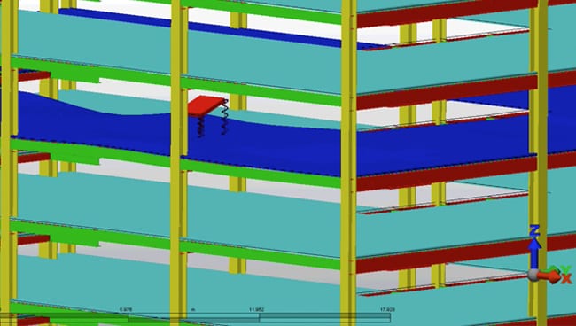
Analysis of vibration modes is a critical component of a design, but is often overlooked. Structural elements such as complex steel floor systems can be particularly prone to perceptible vibration, irritating building occupants or disturbing sensitive equipment.
Inherent vibration modes in structural components or mechanical support systems can shorten equipment life, and cause premature or completely unanticipated failure, often resulting in hazardous situations. Detailed fatigue analysis is often required to assess the potential for failure or damage resulting from the rapid stress cycles of vibration.
Detailed seismic qualification also requires an understanding of the natural vibration modes of a system, as the large amount of energy acting on a system during seismic activity varies with frequency.
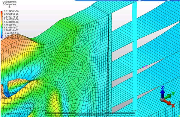
Detailed modal analysis determines the fundamental vibration mode shapes and corresponding frequencies. This can be relatively simple for basic components of a simple system, and extremely complicated when qualifying a complex mechanical device or a complicated structure exposed to periodic wind loading. These systems require accurate determination of natural frequencies and mode shapes using techniques such as Finite Element Analysis.
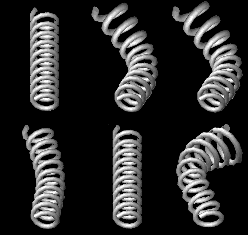
Vibration Characteristics of a Spring
Any material or structure is susceptible to vibration, but many react in different ways. This spring animation displays the twisting and bending that can occur in components of buildings and equipment when exposed to stress and vibration.
VIBRATION ANALYSIS AND FATIGUE:
Structural Components
Modal Analysis of Structural Systems
Specifications for rotating equipment with substantial dynamic loads often require that no structural modes occur in specified frequency ranges. Dynamic analysis of complex floor systems is often substantially complicated, and computer finite element methods are called for.
Rotating equipment was a concern during the design of tanks in an industrial process. These large tanks were to be subject to substantial dynamic forces, and required significant vacant space underneath for piping systems. Finite Element Analysis was used to model a variety of support and restraint systems for each of the tanks. The final system was designed to minimize tank movement, and to reduce fatigue in the system.
HGC has assisted mechanical engineers on numerous occasions when developing support or restraint systems for equipment or machinery with substantial dynamic loads. A complicated support structure was required for a packaged refrigeration system, designed to minimize vibration impact on both the equipment and on the supporting roof structure.
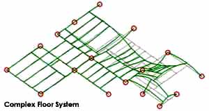
Vibration Mode of a Complex Floor System
An FEA reproduction showing the stress points and vibration properties in a complex system.
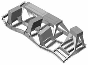
Packaged Refrigeration Support System
Support for a refrigeration system designed to protect from high levels of vibration impact.
Fatigue Analysis
Although simplified “cookbook” methods for fatigue analysis work for simple cases, the bewildering complexity of many structural systems can result in complex vibration problems. Finite Element Analysis is an effective tool for these cases. Designing systems so that natural frequencies are not matched by anticipated excitation frequencies is often critically important.
A design called for a sign to be cantilevered out over the parapet wall of a building. HGC assissted the structural engineers with modal analysis using Finite Element Analysis techniques of the preliminary design concept. The analysis revealed that the design was prone to a torsional vibration mode which could place substantial stress in the supporting members under a gusty wind, or cause the sign to impact the parapet wall.
Further analysis revealed that fatigue problems at some of the joints could easily develop, leading to a potentially hazardous situation.

A sign that required Modal Analysis using FEA techniques to predict vibration and stress

Modal Analysis indicating stress levels and potential failure points.
Seismic Qualification
Detailed seismic qualification is possible using the techniques of Finite Element Analysis. The seismic qualification of a support stand for an automatic control valve in an industrial process was critical for the safety of workers in the event of an earthquake. Finite Element Analysis methods and modal analysis was performed in order to ensure the integrity of the component and the attached piping.
Once the system was accurately modeled, a simulation of a typical earthquake was possible, allowing the design to be qualified.
With increasing degrees of system complexity, Finite Element Analysis techniques become an important step in seismic design and qualification.
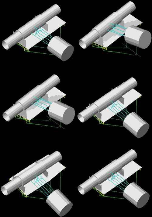
Fundamental Torsional Mode of a Valve Support Stand, shown with idealized valve and piping
Vibration forces were a potential threat to the integrity and safety of this automated control valve. HGC used FEA to model the system and allow for seismic qualification in the event of an earthquake.
Vibration Isolation
The best solution to a vibration problem is often to carefully design an isolation system for the vibration source equipment using readily available or specifically designed isolation components. HGC has assisted mechanical engineers on many occasions when developing support or restraint systems for equipment or machinery with substantial dynamic loads. A complicated support structure was required for a packaged refrigeration system, designed to minimize vibration impact on both the equipment and on the supporting roof structure.

Sensitive Refrigeration System that Required Isolation
Shock Isolation
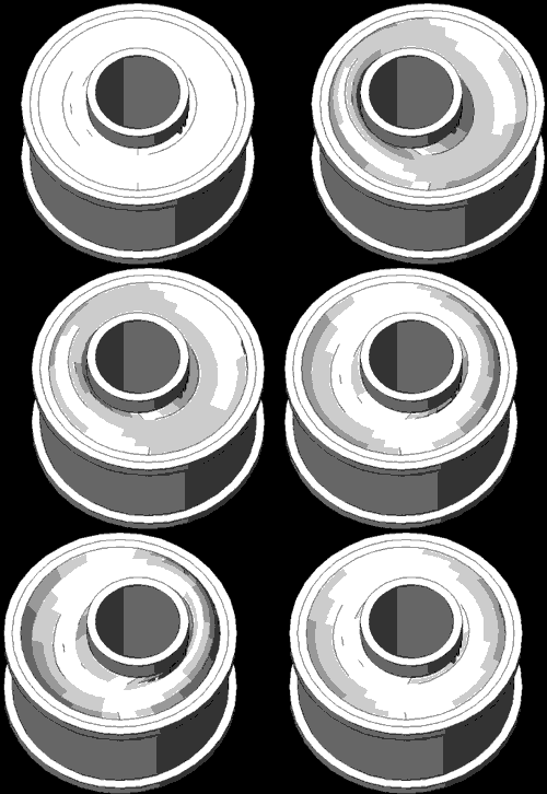 When hydraulic material moving equipment was employed to rapidly unload rail cars in an industrial process, substantial dynamic loads were introduced into the support system. This led to rapid failure of rubber vibration and shock isolation components. Using Finite Element techniques, HGC was able to design improved isolators to withstand the applied forces.
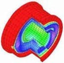
The colour coded cross section illustrates the stress distribution in one revision of the improved isolator design, A new design concept iImproved the design of shock isolation components by Finite Element modeling:


