How to Measure ASTC ratings of Specific Sound Transmission Paths

From STC to ASTC: How Canadian Building Codes Now Address Flanking Sound Transmission
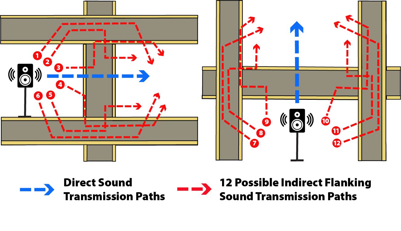
For decades, Canadian building codes only referenced the STC (Sound Transmission Class) rating to regulate sound transmission between spaces; however, between 2015 and 2020, many of the codes were revised to include an additional reference to the ASTC (Apparent Sound Transmission Class) rating of a demising construction – which considers not only the assembly between two spaces, but the junctions around the assembly as well (i.e., indirect sound transmission paths, or “flanking”).
While these codes stipulate certain scenarios where the indirect sound transmission through the junctions is expected to be sufficiently addressed (e.g., drywall ceilings interrupted by the demising wall), and thus an STC rating is sufficient to certify code compliance, other building configurations require the field measurement or calculation of an overall ASTC rating of the demising construction in order to certify code compliance. The direct sound transmission through the assembly (the STC rating) and the ASTC ratings for each specific flanking path combine to provide the overall ASTC rating of the demising assembly. Click here to read more about STC and ASTC testing.
There are 12 possible flanking transmission paths which arise from the four adjoining constructions to the demising assembly (i.e., if the demising assembly were a suite-to-suite wall, the four adjoining constructions are the ceiling, the floor, the exterior wall, and the corridor wall). See graphic below.
There are two ways to determine the ASTC rating of a demising construction: field measurements, in accordance with ASTM E336-20, and calculations in accordance with ISO-15712 and ISO-12354. While the former method is well-established throughout the acoustical consulting industry, it is not always possible to conduct field measurements (e.g., prior to construction of the building). In such cases, the ASTC rating of specific flanking paths (and an overall demising construction) can be calculated based on the STC rating of the flanking assembly, the room geometry, and the velocity level difference between flanking elements.
Using velocity level difference to calculate the ASTC rating of specific flanking sound transmission paths
The velocity level difference can be used to characterize individual flanking paths and to calculate their ASTC ratings. Similar to how the STC rating incorporates the difference in sound levels on either side of a partition, the velocity level difference is calculated by taking the difference in vibration velocity levels on either side of a flanking transmission path (e.g., the floor on the source side to the demising wall on the receiver side).
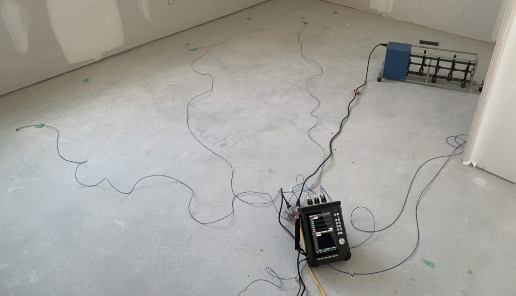
Multiple sensors and excitation source setup (using tapping machine as the source) for velocity level difference measurements
To measure velocity level difference, vibration velocity levels are measured in both a source room (Room A) and a receiver room (Room B). Multiple sensors are set up across the flanking elements in both rooms such that an average can be taken of the levels in each room. In the source room, the flanking element is excited by a vibration source, such as a tapping machine, an electrodynamic shaker, or a hammer. The velocity level difference is found by subtracting the average velocity levels in the receiver room from the levels in the source room. After measurements have been taken by exciting the element in Room A, the excitation source is moved to Room B and the same process is undertaken, now with Room B as the source room and Room A as the receiver room. The final velocity level difference between the two elements is found by averaging the two sets of measurements.
Structural Reverberation Time
In some cases, finding the velocity level difference is sufficient to calculate the ASTC rating of the flanking sound transmission path. However, in other cases (e.g., heavy homogeneous flanking assemblies such as poured concrete), the transmission through the flanking element is also defined by the structural reverberation time. This is due to the variation in sound transmission through a heavy, homogenous element based on various edge conditions and structural connections (e.g., a large poured concrete floorplate with lightweight walls above vs. a poured concrete floorplate with various poured concrete walls above limiting vibration across the floorplate).

Structural reverberation time is measured by striking the flanking element with a sharp vibration impulse. With sensors set up across the room in a similar fashion to the velocity level difference measurements, the element is struck at. After each strike, the vibration levels rapidly decrease (similarly to a room echo), which represent the structural decay of the element. This decay in vibration level is measured by the sensors affixed to the element. The reported value for structural reverberation time (RT60) is the time it takes for the vibration levels to decay from 5 dB below the peak impact vibration level to 65 dB below the peak.
Vibration Reduction Index
In such cases where the sound transmission through the flanking element is influenced by the site-specific structural decay, both the velocity level difference and the structural reverberation time are included in the calculation of the flanking path’s vibration reduction index. During the design phase of a building, the vibration reduction index for the flanking junction can be sourced from published test results of identical junction measurements in different buildings, or in some cases, calculated based off theoretical formulas; this allows the engineer to then calculate the ASTC rating of a flanking path during the design phase based on this vibration reduction index and the flanking element geometry without needing to conduct measurements in the building being designed (provided vibration reduction data for the junction is available).
The benefit of the vibration reduction index
By introducing vibration reduction indices, it becomes possible to calculate specific ASTC ratings for each flanking path during the design phase. This is greatly beneficial where code compliance cannot be inferred only from STC ratings for the demising assembly. Additionally, if an ASTC test result for a demising assembly does not meet the target criteria (e.g., building code minimum ASTC requirements) and is well below the expected direct sound transmission (STC rating) of the assembly, determining the ASTC rating of each individual flanking path can determine the specific transmission path limiting the overall test result. For example, HGC recently performed vibration reduction index testing for a suite-demising wall well in excess of STC-50; however, the ASTC test result was ASTC-42 due to sound transmission through flanking paths around the suite-demising wall. By measuring the vibration reduction index of the different flanking paths, the level of the sound transmission between suites could be individually characterized, and it could be determined that sound transmission through the floor was limiting the overall performance to ASTC-42. From this point, recommendations were made to increase the performance of the floor-to-floor flanking path, thus improving the performance of the entire assembly.
Lastly, it is important to note that not all flanking paths can be identified from testing velocity level difference, such as holes in caulking, flanking through electrical conduits, and others. However, in many cases the velocity level difference and vibration reduction index can provide valuable insight into the acoustical shortcomings of an assembly and the adjoining constructions.